

IRLP
Radio
Vintage

Live Status
VK2YLD
Steve...
Kurri Kurri,
New South Wales
Australia
email - vk2yld at dodo.com.au
REAL radios glow without smoke.


This radio was a score from 'Evilbay' in a rather delapitated state. No final bottles and a couple of free rat nests. After a good cleanout I hunted around for some finals. The chassis was still original apart from someone's attempted repairs and 'if there's an adjustment it must be tweaked' realignment. Some time surfing 'the bay' turned up nothing in Australia, and some 6JS6s in the states for a humungous price, plus post of course. On to the data books....
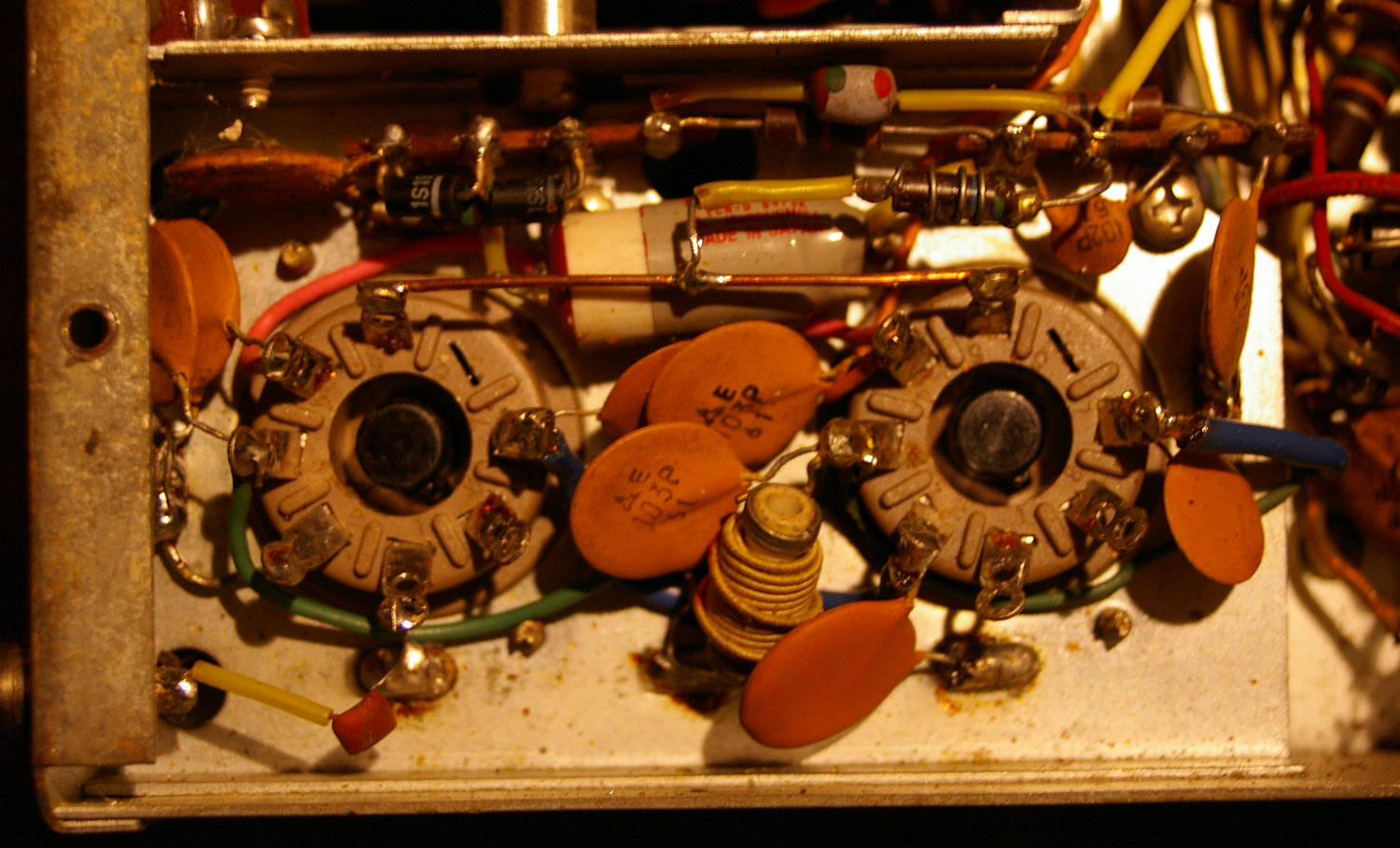
There is some litrature about dealing with swapout to 6146s and as I have a heap in the junkbox, this was a good option, until... Further reading the data books I found a couple of 6DQ5s, an old TV sweep tube from way-back, and the data sheets were a near perfect match for 6JS6s right down to the inter-elecrode capacitances. Using these means not too many nasty circuit mods, only a basing change to 'octal' and a minor rewire. If you try this be warned...RCA tubes are too tall and the plate caps might short to the HV cage lid! (700+ volt SPLAT!) The tubes I have are GEs, and they fit OK.
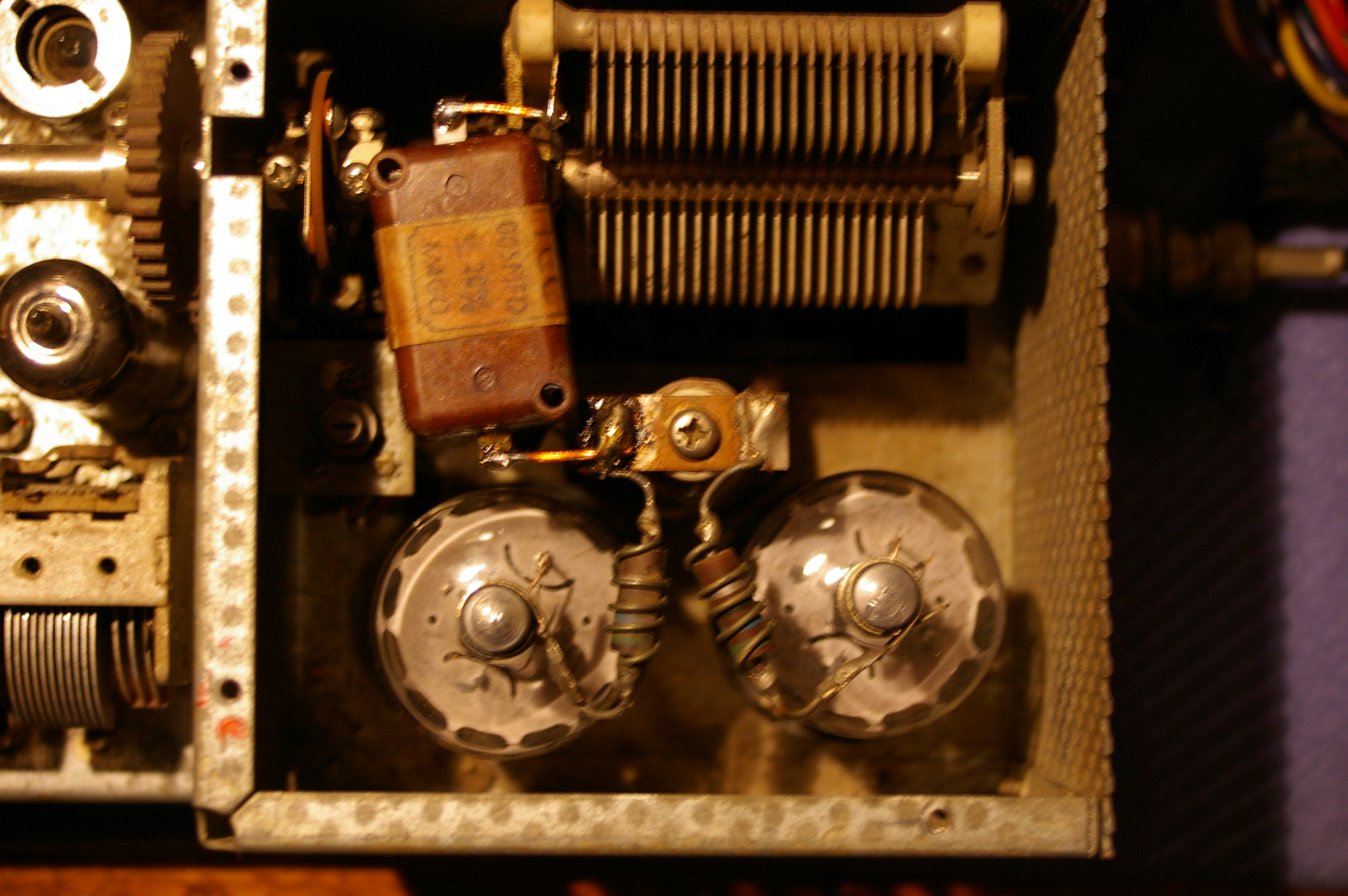
A little surgery and the new sockets are in and wired. The original holes even worked! Whilst the tubes were out, I also fitted the neutralising mod (new cap) as I figured it would probably help. Whilst fiddling here, replace C40 & C55 or they will give you grief later by melting down the new finals. The pic at left shows the new bases in and ready for action. Note the copper wire strap on the tube's G1 pin is fed in the centre with the inductor from the driver anode. This should help to keep the tubes balanced on the high bands as phasing errors start to creep in with parallel tubes as frequency rises. I also added an old computer fan to the back of the HV cage, and powered it from the 12v heater supply via single diode rectifier and capacitor filter. The 'Mic Gain' pot got ripped out and replaced with a switch-pot. (Another dirty trick!) The switch is connected in series with the AUX socket on the back panel and the final tube bases. (that blue wire there on pin-7) With this arrangement the transverter still gets heater voltage and can still control the 200s heater BUT.... if you are 'just listening' for a while, turn the Mic Gain to minimum and 'click', the finals go cold and the fan stops...nice... Smoke test completed and good output returned after a couple of new small tubes, some new caps in the power module, re-alignment and neutralising.
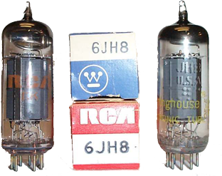
More page flipping and guess what... Another substiute materialised... This little number is the 6JH8. It's what they call a 'Sheet beam' tube and is used in colour TV sets for syncronous detectors and burst gate. Same construction, but different pin-out, drat! Anyway, these were found on evilbay for $15US for 5!... At that price I gotta try it.. A quick socket rehash done by carefully cutting the pattern close to the socket lands, and laying in jumper wires to reconfigure the circuit. Make small, clean cuts that isolate the socket pads, so it can be undone later if needed. The test run got a good null straight up, very close to 50% of trimmer travel. SSB now sounded like SSB, heaps better.. A quick tweak of the alignment and all crystals replaced (why not... it needed the optionals anyway) and the rig is returned to fully operational. Great reports on-air and a good receiver, not brilliant, but good... hmmmm... maybe the front-end... hmmmm... where's that data book again...
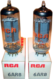
FOOTNOTE:- Since looking at the data books again and doing more research, another candidate has come to light.. It's a 6AR8, a clone of the 6JH8 with the same specs and pinout, so if you can't find a 6JH8, try looking for a 6AR8. It'll do the same job and even though it's a bit pricier than the 6JH8, it's still cheaper than a 7360 (if you can find a good one!)..
I set the PA final voltage at the 600v tap and set the idle bias to 60mA and all seems well. Good carrier on tune up to about 170W PEP, but the SSB sounded like rubbish. Really muddy sounding, and the modulator balance was dipping but couldn't get proper carrier null. The 7360 modulator tubes are as rare as rocking-horse poop, and twice the price so another swap was in order. I looked at the solid state option, as there are drawings for solid state replacements that simply plug into the existing 7360 socket. The thought of introducing "sand" into the signal path....Naaah... Oh well, back to the old drawing board, err data books...
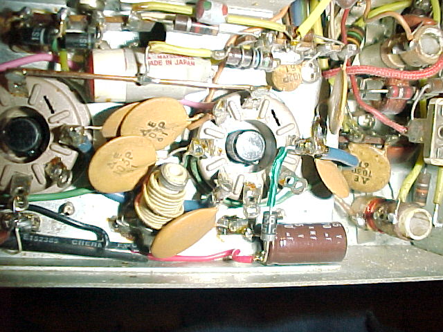
From the circuit extract at left, (click for larger image) the 120R 1w resistor across V4 filament gets removed with the 7360 replacement to balance the heater current again. Replace the resistor with another 0.047 ceramic bypass cap. See where they buried it at right. V107 and V4 now draw the same current and so the shunt is no longer required. (V107 is the 6JH8)
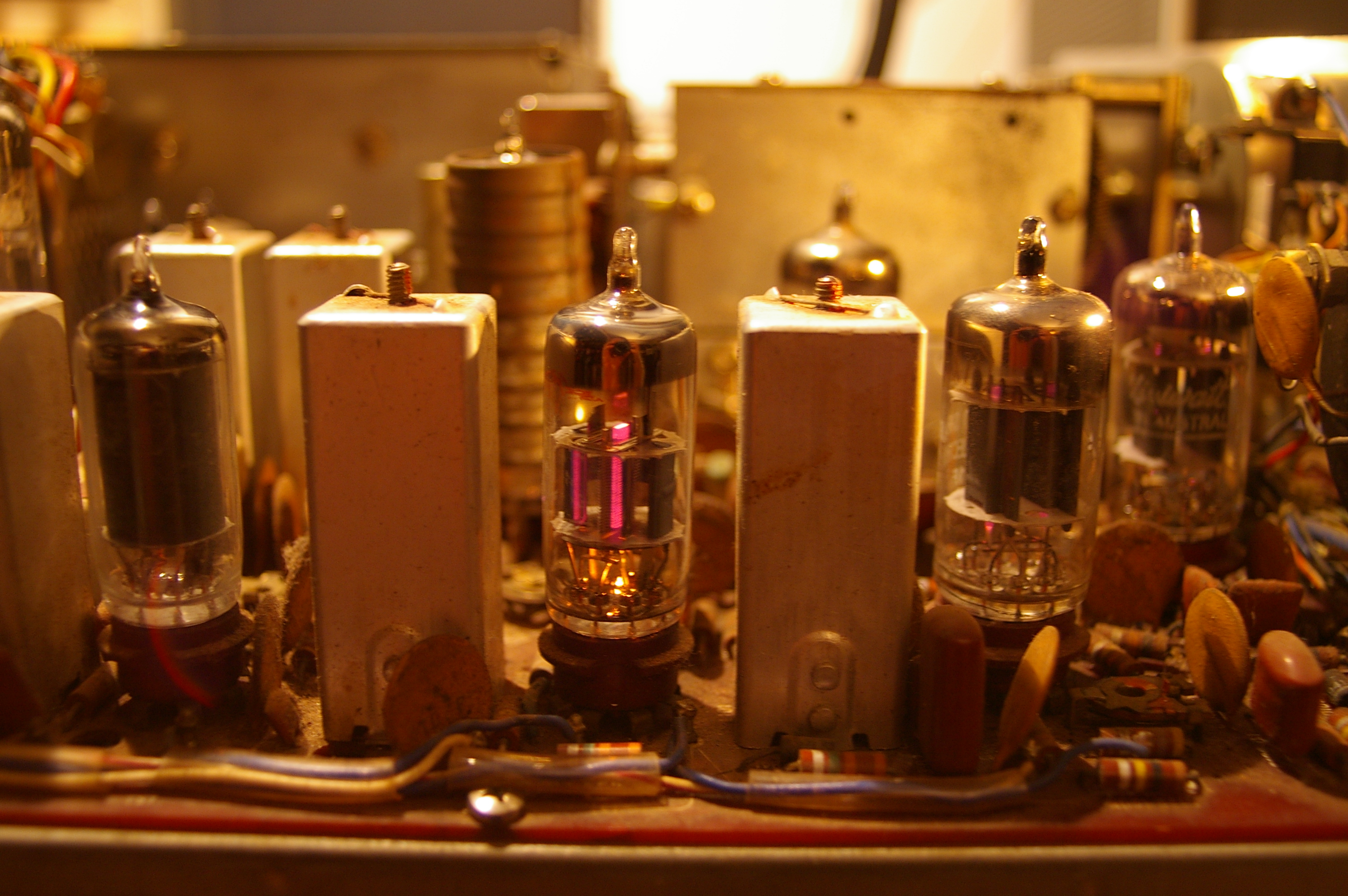
It Lives!! During the re-alignment. The 6JH8 sits near the VFO cage inside the rusty shield. The filament current is lower than the 7360 (0.3 vs 0.35A), so a balancing resistor has to be removed from the filament circuit. See above for details.
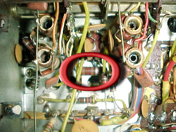
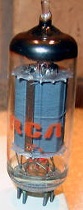
Inside the PA cage with the 6DQ5s well at home and the bodged coupling cap (500pF) glued in place as the original released its 'Magic Smoke' and stopped working. This 3Kv cap will get replaced when I source a better one to do the job.
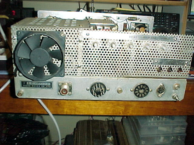
Here is a look at the fan installation. At right is the simple 1/2 wave rectifier and smoothing cap sniffing power from the heater line. Not shown is a .01uF ceramic that I placed across the smoothing cap to bypass RF from the fan power line. At left is the fan position on the rear panel. I decided not to worry about a guard on it 'cos you wouldn't stick your hand round
there with it switched on. (would you?) I didn't worry about enlarging the holes in the rear panel behind the fan, it gets up a good enough airflow as standard. You can see on the back view, another little mod... the 5 pin DIN socket where the ext VFO jack was.. well.. It's a TNC connection... works good too.. Even does a good job when connected to the computer sound card and running digital modes (PSK & SSTV). I get a few wierd comments though when in a QSO and let on what the rig is... Bottle radio hits the computer age!!
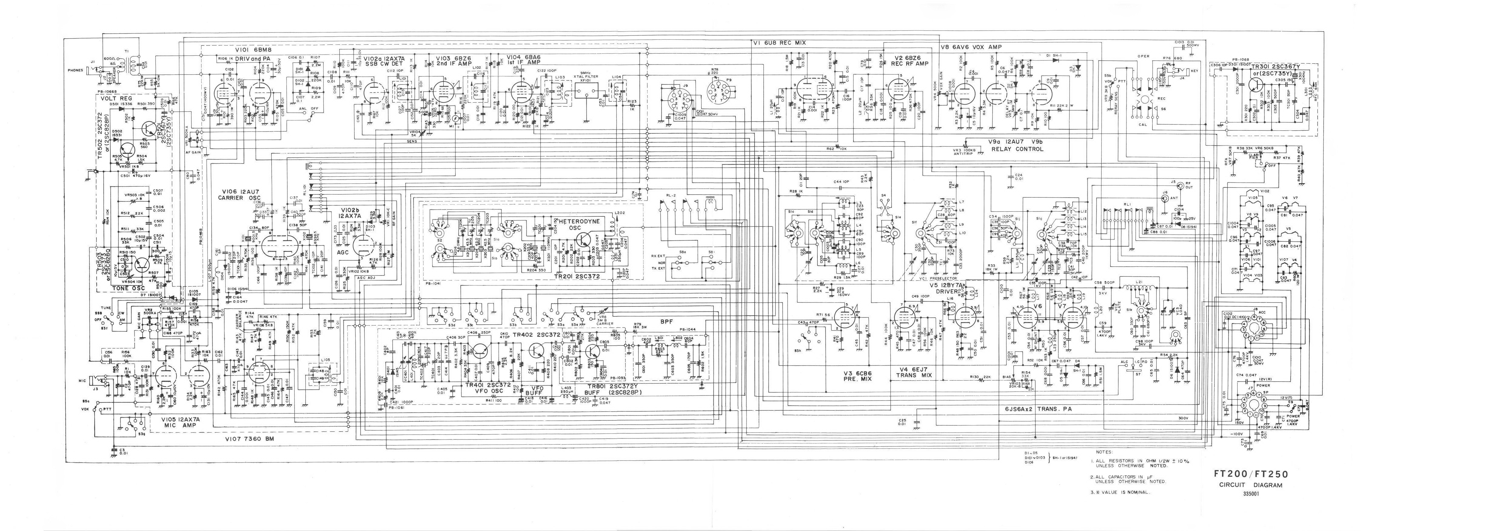
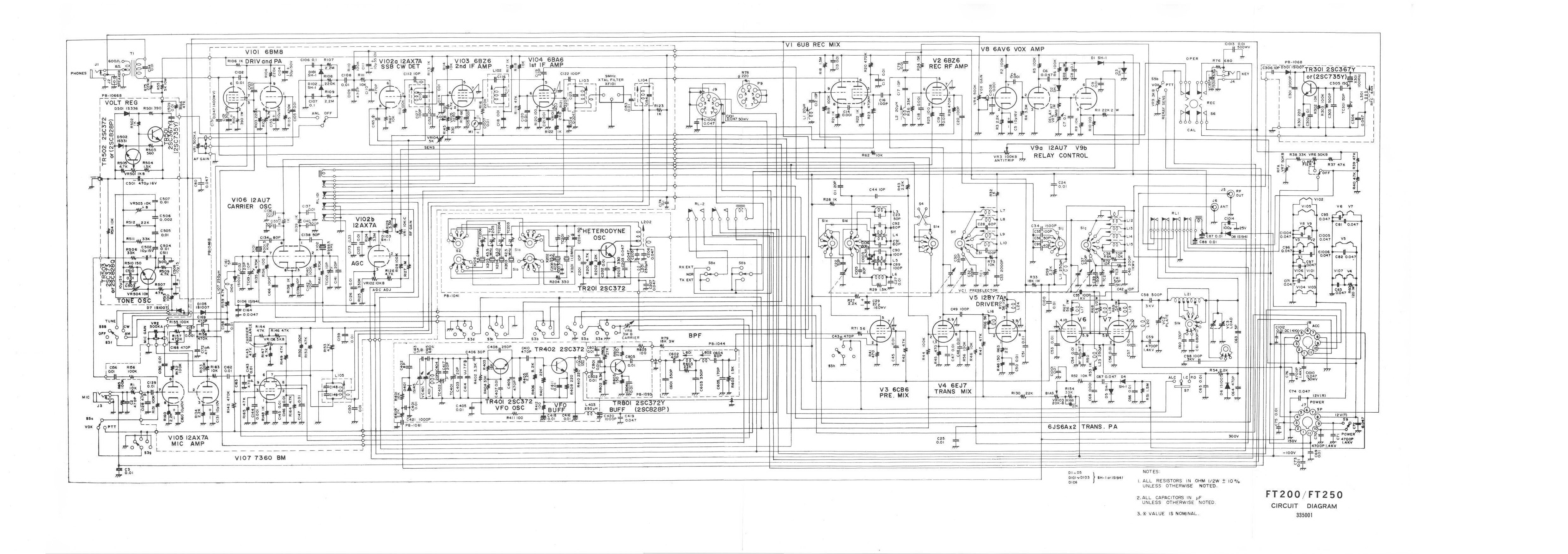
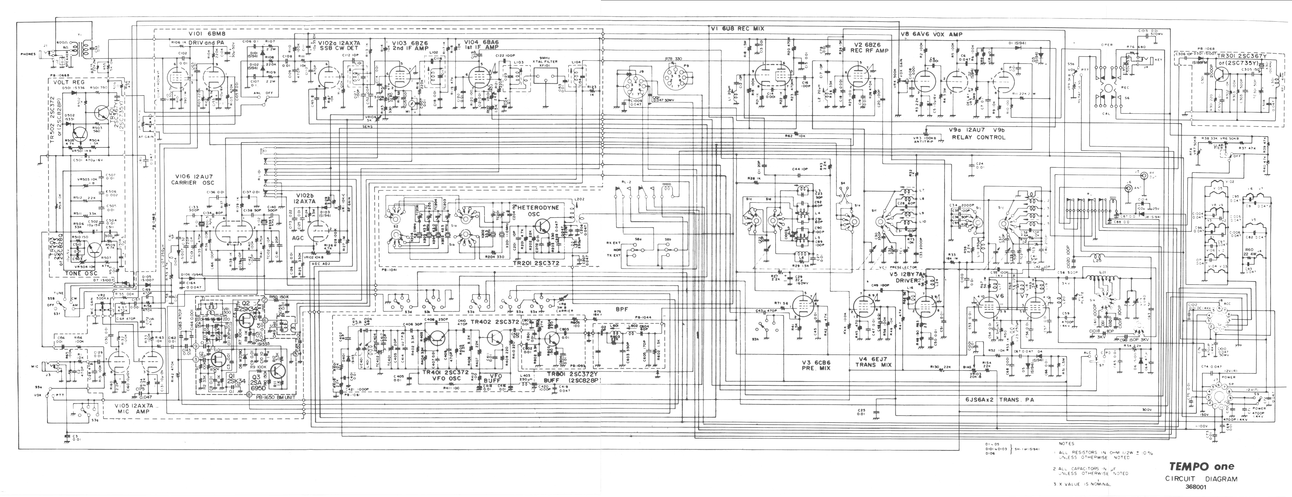
Schematic
Tempo 1 with
Solid State BM
-Single Sheet-
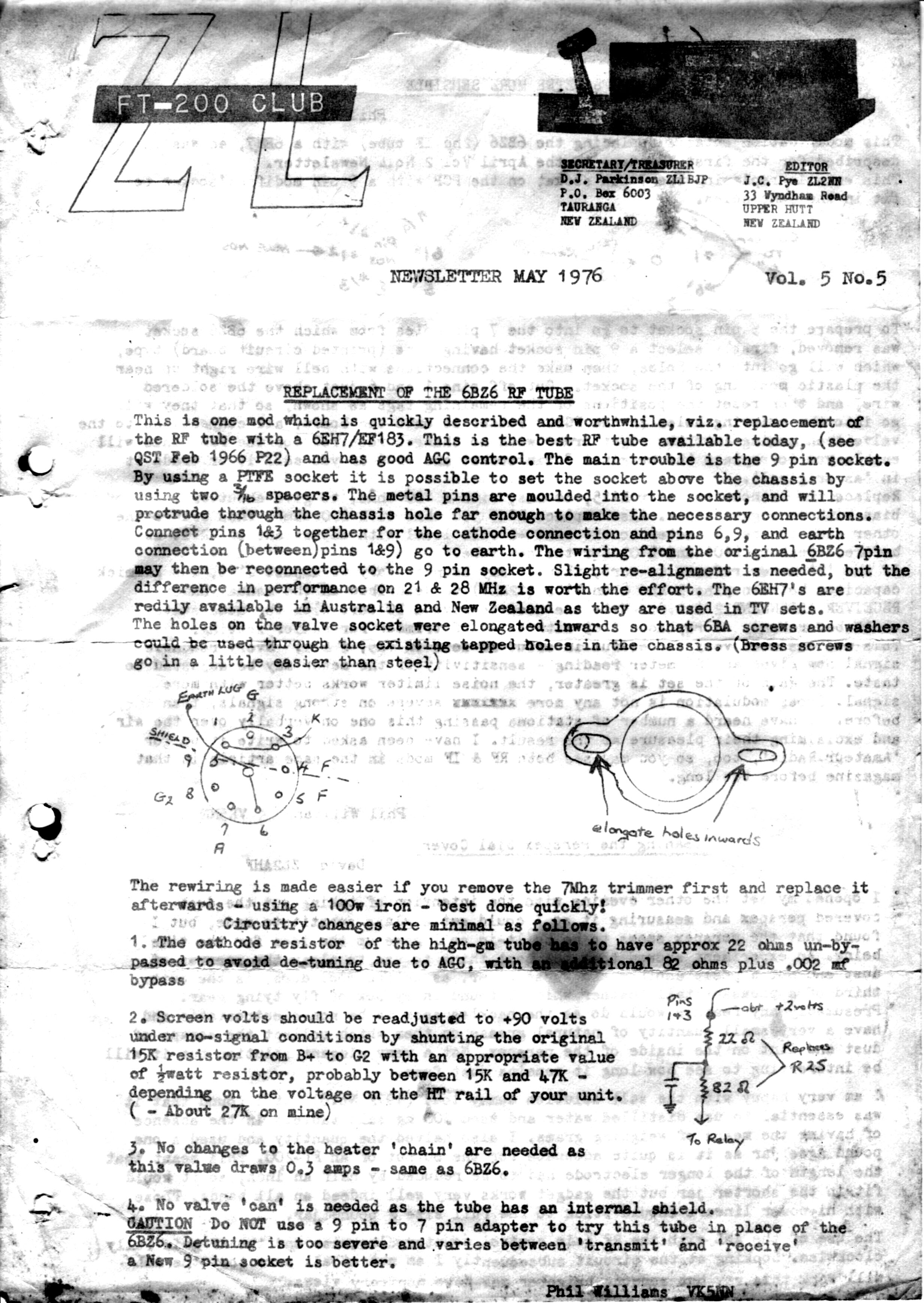
This receiver is not bad, but could be better. If you are game.... In the above information panel there is a document called 'ZL5 Mod Sheet'. Follow this carefully and make the changes listed to improve the receiver... As the 6EH7 is a fairly common tube from the dim, dark TV days, I have a heap of them in the junkbox, so this was a zero cost upgrade. I have put up the data sheet for the 6EH7 that replaced the 6BZ6 if you need it. A minor re-tweak of the front-end alignment is needed after the modification has been done. The instructions talk about sitting the new socket above the chassis on standoffs, but I didn't do this. I removed the old socket and hit the hole up with a friendly old Q-Max cutter to open it up to B9A size, and fitted a new recycled socket. Drill a couple of new screwdown holes and reuse the self-tapping screws from the old socket. The better gain figures (GM of 12,500) from this tube on the higher bands are good for use with the transverter as this uses the 10M band on the radio. Take a look at the RF Amp Mod page if you're game....
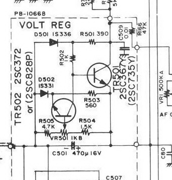
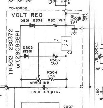
Original circuit on the left shows TR1 & TR2.. So rip them out, along with R502 & R505. Replace R505 with a wire link and insert the 7805 into TR501's slot with Input to 'C' pad, Output to 'E' pad and a small length of insulated wire from Com or Adj to TR502's 'B' pad. You end up with the circuit shown at right, and the 7805 runs well without needing a heatsink. I left D501 (11v Zener) in place as the input of the regulator is coupled via the 47K to bias off the front-end whilst transmitting. You can remove R503 & D502 as well if you wish, but I left them there.
Whilst going through the alignment process, I looked at the setting of the 9v regulator board. After 30mins warmup, the voltage was set at 9.00v.. After a while, this voltage was re-measured and has moved to 8.7v. Letting the set cool down then powering on again, it measured 10.6v and slowly fell as the radio warmed. This may have been part of the reason the set drifts so much until it's temperature settles as the VFO runs from the regulated 9v rail.. I changed the transistors and all the resistors in the regulator as the whole lot were out of tolerance. Still not real good and still drifting over a wide voltage range. One quick thought... how about a voltage reg IC?? Digging in the junkbox I found a likely looking 7805 regulator, and as the original first transistor is a regulating element with the second as the control, the 7805 drops into the one's slot, with the 'Adjust' or ground terminal spanning across to the other tansistor's base connection to pick up the adjuster pot. Part of the voltage divider that is around the 'Set' control is removed (the resistor to ground) and bypassed to give the right control range and Bingo! 9.0v from cold to 9.13 after 1.5 hours.. Much better...
Schematic
Single Sheet
ZL5 Mod
Sheet for RF Amp
6EH7
RF Frontend
replacement Tube
Schematics
(4 Sheets Zipped Up)
Operators
Manual
A mod I have done is to the power supply. Apart from the usual re-cap and cleanup, check all the rectifier diodes. Grab a meter and test them carefully. I had some trouble with mains hum on the HT and this put a bunch of unwanted artifacts in both the transmitted signal and the receiver. Turned out that apart from the junk caps, one of the HT rectifiers was shorted too. I replaced this and made sure all the diodes had bypass caps on them too (ceramics) to make sure that any switching noises are taken care of too.
If you look at the circuit drawing again for the power supply, the incomming line power goes into the power supply, then up to the radio power switch via the umbilical cord and back. Apart from this putting LIVE line voltage in the radio case, if you look at where the cables go inside the radio (2 yellow wires inside a yellow pipe), they can get skewered by the case screw that goes into the lower front panel (zzzzzt!). After repairing these wires (CHECK YOURS!) I added a small 12v transformer, bridge, filter cap and a relay (torn from an old microwave oven) with contacts rated at 240vAC 4A. The contacts of the relay are on spade lugs and the coil is solder posts. I removed the mains from the radio connector and re-wired the connector to take the 12vDC to the radio and back. The front panel switch and wiring stays stock, but only switches the 12v to the relay which in turn switches on the juice. The 12v transformer is on all the time but is no worse than any other wall-wart type transformer polluting the walls of the house. (cordless phone, mobile charger, etc...etc...) It's worth it for the safety of both the radio AND the operator!
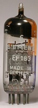
6AR8
Sheet-Beam Tube
7360
Original Balanced
Mod Tube
6JS6
Original Final
Tubes
6JH8
Sheet-Beam tube
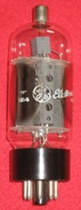
6DQ5
Sweep Tube
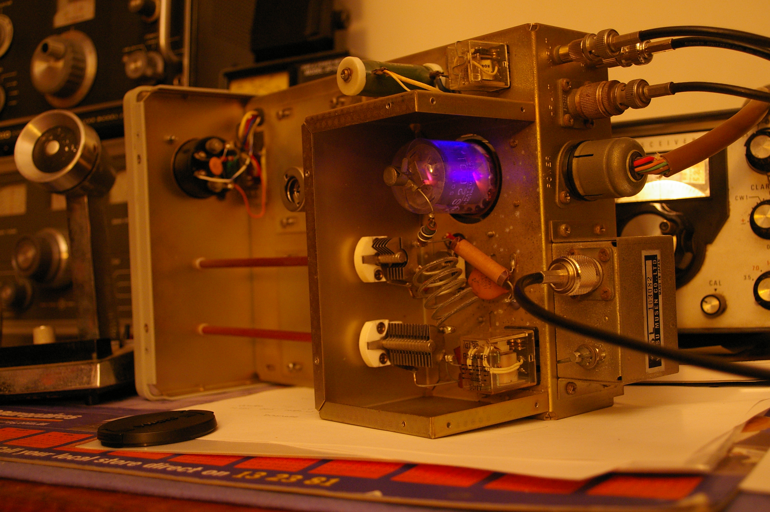
She can't take it Captain! Transverter all Gassed up! Impressive.... considering it was in receive when these photos were taken, but the tube's dead Fred!
As this box used to be run from an FT-101, the bias arrangements for the final are different to the FT-200. This results in insufficient bias voltage when receiving, to cut-off the final. Still drawing current, it roasts.... Bias was measured at -8v on receive just before the glass melted! A minor adjustment to the voltage divider chain and a quick recheck WITHOUT a tube fitted now shows -45v. Better... A new 6146B fitted in place of the glob (ex S2001) and bias readjusted for transmit, now completely cuts-off the final when receiving. No more toaster.. Works well on 6M now too.......

Modifications
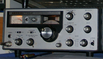
Restoring the Yaesu FT-200
Data Sheets & Info...
The Power Supply
The 9 Volt Regulator
The Receiver Front-end
The 6M Transverter
