

IRLP
Radio
Vintage

Live Status
VK2YLD
Steve...
Kurri Kurri,
New South Wales
Australia
email - vk2yld at dodo.com.au
REAL radios glow without smoke.


")


This amplifier came onto the bench in a rather sick state. It had been performing normally and then all of a sudden the power level dropped away and the protect lamp came on and the box shut down. A quick hookup to verify the problem showed that a key-up with no drive and it was happy, but as soon as you gave it drive at only 5w it tripped the protect and shut down. I also noticed that the right hand meter lamp was out and due to the design it was near impossible to read the meter without a torch. Also noticed the 'Band Down' button was not working.
I removed the covers and as the box only tripped out with drive I figured the problem had to be one of the PA decks either low power or dead and the protect was due to PA unbalance.
There is a cable from the power combiner to the main CPU that causes protect shutdown on PA imbalance. I removed this cable and tried again with 5w of drive. The output went up to about 30w with 5w drive. Way low power. A quick check of the bias currents showed that PA1 was drawing current from the 47v rail when not keyed up. PA2 was normal with no draw till keyed.
First order of business was to replace the meter lamps. The perimeter screws are removed and a quick look at the way the front plastic is fitted around the LEDs, the removal has to be careful to avoid knocking into an LED as it would take ages to realign all the LEDs to get the front back on! After removal of the screws, grab the front panel and pull STRAIGHT forward.. easy, yes? Now the meters can be removed from the framework and opened up for lamp replacement. Place a new piece of tape to hold the covers on the meters and carefully line up the front and re-install it. One job down...
Now on to the bigger problem, the PA block has to come out. You can get to the transistors by removing the four hold-down screws and unplugging the coax leads, then flipping the PA block over on top of the power supply, but I figured that the work I had to do here needed the removal of the block from the chassis completely. After removal I removed the connections from the power splitter to each PA and removed the two PAs and power combiner as a unit for cleaning and inspection. There were quite a few dry joints from the factory assembly and a couple that were very close to failure...
When I had the PA block on the bench, I happened to notice the power combiner board had burnt resistors. I am pretty sure that happened when I was testing the PA sides to see which one was faulty and the power fried the hybrid balance resistors...OOoops..
I pulled the pills from the PA boards and tested them on my little auto tester... One was leaking C-E which accounted for the current drain when unkeyed and another had a gain of 12 with the last two at 26 and 25 (from PA2).
The 2SC2652 transistors are now unobtainium unless you want to try a fake or two from an overseas supplier on a certain auction site. I found an article on an Icom linear IC-2K, and they replaced the pills with MRF448s. I managed to find a supplier in the USA and whilst not cheap, they were a reasonable price (except for the crap exchange rate AUD -> USD). A replacement set of 4 was ordered. Boards cleaned up and waiting for parts...
Not quite as easy as was first thought.. The main CPU battery had quietly leaked its contents into the band down button switch. The battery and switch were removed and the board cleaned with 99% IPA to check the traces for damage.. all good. A replacement switch was stolen, errr, borrowed from the Antenna-4 button as this is not in use. Both CPU boards then got battery holders and new CR2032 batteries....
Next off the list is the modifications to be done.. I found a list of suggested mods on 'mods.dk' site and as I know the protect board is very sensitive and can trip out when there is nothing really wrong, like a voice spike on SSB with full drive etc.. I did however find a problem with their list in one section where they had the wrong pin number to insert a new resistor. That mod had already been done on this unit, but the additional cap on the SWR trip had not been done. I added this mod and double checked the rest of the mods.
In the post was a package from the USA with the replacement pills. Quick test verified the gains all matched as per the numbers on the pills.. All good..
While the box was in bits I checked the power splitter out and all the parts were serviceable, so that was refitted to the PA block.
Now for the PA decks.. The components on the boards were all checked out and appeared to be in tolerance, so all ok to proceed. The thought of destroying very expensive parts lurked in the mind... especially when flattening the feet. They were pretty close and didn't take too much work. A piece of wet and dry 600 grit sandpaper is stuck to a piece of glass and the transistor heatsink pads (feet) are carefully sanded flat to make sure they contact the heatsink fully. A THIN smear of thermal grease is all that is needed for good heat transfer. Too thick a layer of grease can become and insulator and cause the feet to hydro-lock and bend slightly when screwed down. Premature failure will result. Both decks done and ready for business. The combiner board got new resistors and the block reinstalled in the amp.
Now the fun bit starts.. I put a lab power supply, current limited to 100mA set to 30v, on to each PA main power rail to check for shorts before I blow the lot to bits... Neither PA drew current, so I figured it was safe to give it the full power supply. I powered up the unit and made sure the 47v line was correct. Then I clipped the 47v lines to the PAs via 500mA meters ready to set the deck bias.
The good book says no drive and wait 60Secs before setting the current. I thought it was strange that the PA idle current is not stable, it slowly rises with device temperature. That is why you have to wait. I was aiming for 175mA idle each side and to get the decks balanced you need to watch both sides at the same time and keep tweaking to try and keep them together. When the 60Sec timer on my phone beeped, I had both nailed at 175mA. (Picture has parallax error!) Remove the meters before you add drive or you will smoke them out..
With that set, time to cross the fingers and toes, turn up the drive and watch for smoke... Stomped on the pedal with the drive at 5w FM and the amp yielded 60w average watts (Bird Watts!).
So after that I cranked the drive to 75w SSB with 2-tone (700/1700Hz) and was rewarded with 600 Bird watts.. cool! No expensive smoke! With the bias at the 175mA mark there was no visible crossover distortion on the scope and the spec-an shows a little IMD3 at about 55dB down on 500 Bird watts output, so I left the settings there.
Last thing to do now is check the alignment of the protect board by the manual and button it up for a final function test.. 2-Tone SSB full tilt and see how long before the temp warning comes up..
The original 2SC2652s were rated 50v 200w, and the MRF448s are rated 50v 250w, so there is some safety margin there to play with as long as the power supply holds its nuts off the ground!
In the manual, there is the alignment section which describes the setup of the protect board. I followed most of this, but with the replacement MRF448 transistors and modified board, setup was not going to be strictly by the book! Power supply overcurrent and fan controls all tested ok, and some adjustments carried out. ALC voltage measured on the rear panel jack tested OK, but with the removal of Q4 (mod) the excessive drive protect no longer trips the amplifier out. Just have to make sure ALC is applied to the exciter to limit the drive. Tuner checked out OK, but is pretty slow to do it's bit and seems lossy when in circuit. Much better to have a good external tuner and leave the internal one off. Would still work OK in a pinch. I think it might be worth looking into that Q4 removal and put it back, but desensitize it a bit to stop trip out at (by the book) 500w output... But for now, JOB JOBBED!!
Resources..

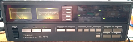
The Yaesu FL-7000 Linear Amplifier
