

IRLP
Radio
Vintage

Live Status
VK2YLD
Steve...
Kurri Kurri,
New South Wales
Australia
email - vk2yld at dodo.com.au
REAL radios glow without smoke.


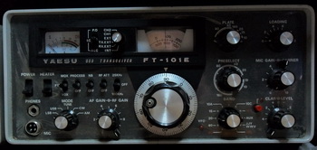


Another boat anchor joined the ranks of my collection when I got this FT-101e. It came with the guise that the receiver was deaf and the transmitter was in an unknown state. At least that's better than the old faithful "worked last time I used it!"
Once on the bench, yep, the box was deaf, not totally deaf, but low. The transmitter looked reasonable but the final valves showed some burn marks on the inside of the glass, so I guess they have had a hard life. I fired up the transmitter and the standing current was low as expected, so I reset the bias to bring up the current and then removed the finals one at a time to check the balance. This came out better than I thought it would with pretty close to half each. Now to try and get some RF out of it. With my dummy load connected and the carrier control raised to give 90mA corrent, I could not get the PA current at dip at all. With any load or tune setting, there was no dip and I noticed that there was no RF output either. Both controls did nothing!
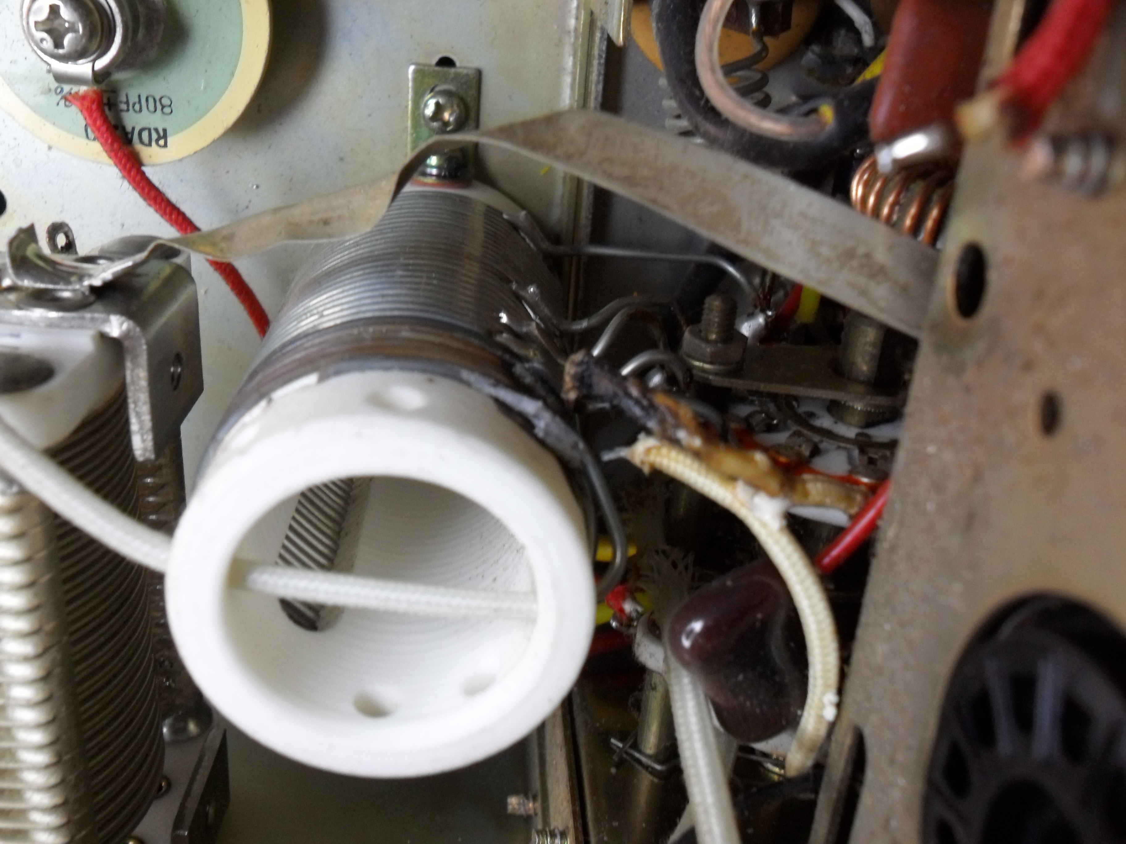
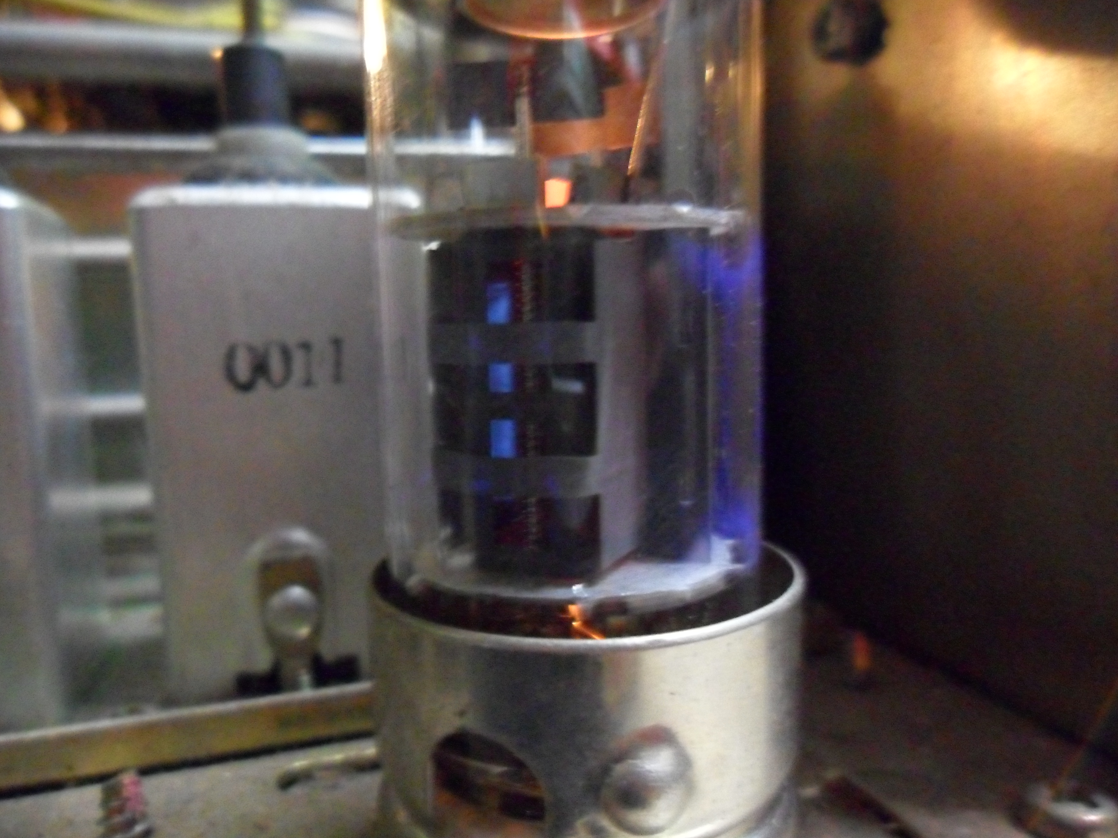
On closer inspection, I noticed that the end of the tank coil was burnt and a wire leading down to the bandswitch had melted. Obviously this had been used either with incorrect tank tuning, a bad load or no load at all and the resulting currents in the tank just fried it. A full stripdown of the final compartment was needed. The high voltage RFC was OK, the coupling caps checked out ok but the tank coil itself was open circuit. With the fried wire replaced, tank coil repaired and cleaned, the switch wafers cleaned and everything reassembled, we have output power and the PA current now dips as it should. I reneutralised the PA and now it loads up on all bands as it should. Even with the original cooked finals, the set brews up a healthy 140W PeP, dropping a little on 10M. I touched up the driver tuning and noticed the 12BY7 flouresces a bit when hit with power. The glow is mostly on the inside of the anode and the inside of the glass. As the valve tests good, I left it in place. Looks kind of good glowing like that, and the glow flickers with modulation and current flow through the valve.
Resources..
One other thing that I noticed, is the two crystal holders on the RF Processor board had crystals in them. These two holders correspond with the Ch1 & Ch2 switch positions on the VFO selector switch and are designed for spot frequencies inside a specific band. They replace the VFO with a crystal locked 'spot' and according to the manual, should be between 8700 - 9200Khz. These two were 27.880Mhz and 27.890Mhz. They are relatively new and have 'FT101' stamped on the side?? Doesn't make sense, so these were removed. All running well now and the output waveform looks good on the CRO and spec-an so only the on-air checks remain to be done to call this one a good thing..
Further to... We had a storm pass through, with ligtning the whole bit, and guess what?? I forgot to remove the aerial from the rig the night before, now the beast is deaf! A bit of poking around under the hood and it appears that the RF Amp FET is smoked... 3SK40M is another obsolete beast from the past. There is two of them in here, one in the front end, and the other in the mixer stage. If I remember rightly, back in the early days of my HF career I did a fair bit of work with Codan Transceivers. These had a dual gate MOSFET in the front end that was the BF981, an N-Channel Dual Gate FET, and with built-in protection diodes on the gates. Comparing the datasheets it looks like this one will do the job nicely, with a little more gain to boot.
After a bit of research on the net, I noticed someone else has had a go with this FET too. I checked in with the foxtango site, and they have a replacement FET on the books, but these are US$9.90 each plus freight and the only info I can gather is that it's a Motorola device, but the part number is not listed. I guess it's a 3N211 by the looks and general gist of other postings, and these are way more expensive than the BF981 (seeing as I have about 15 in the junkbox!!) I tested the BF981 as Earl did his (http://www.earlandrews.com/dgmosmod.html) and the receiver sprang back into life. I didn't have any instability problems, so I didn't worry about the ferrite beads on the drain. To make this a permenant fixture I removed the socket from the board and fitted the BF981 directly into the vacant holes. A bit of creative lead bending and it's good to go again. I will look at replacing the mixer FET too when I get time to do the full re-cap, as I think it will benefit from the extra gain and lower noise figure too. The receiver appears about the same as it was on strong signals, but the weaker ones seem to be way more readable now. The calibration on the 'S' meter was now out, so I reset that and all is well again.
Another Anchor - The Yaesu FT-101E
