
IRLP
Radio
Vintage

Live Status
VK2YLD
Steve...
Kurri Kurri,
New South Wales
Australia
email - vk2yld at dodo.com.au
REAL radios glow without smoke.


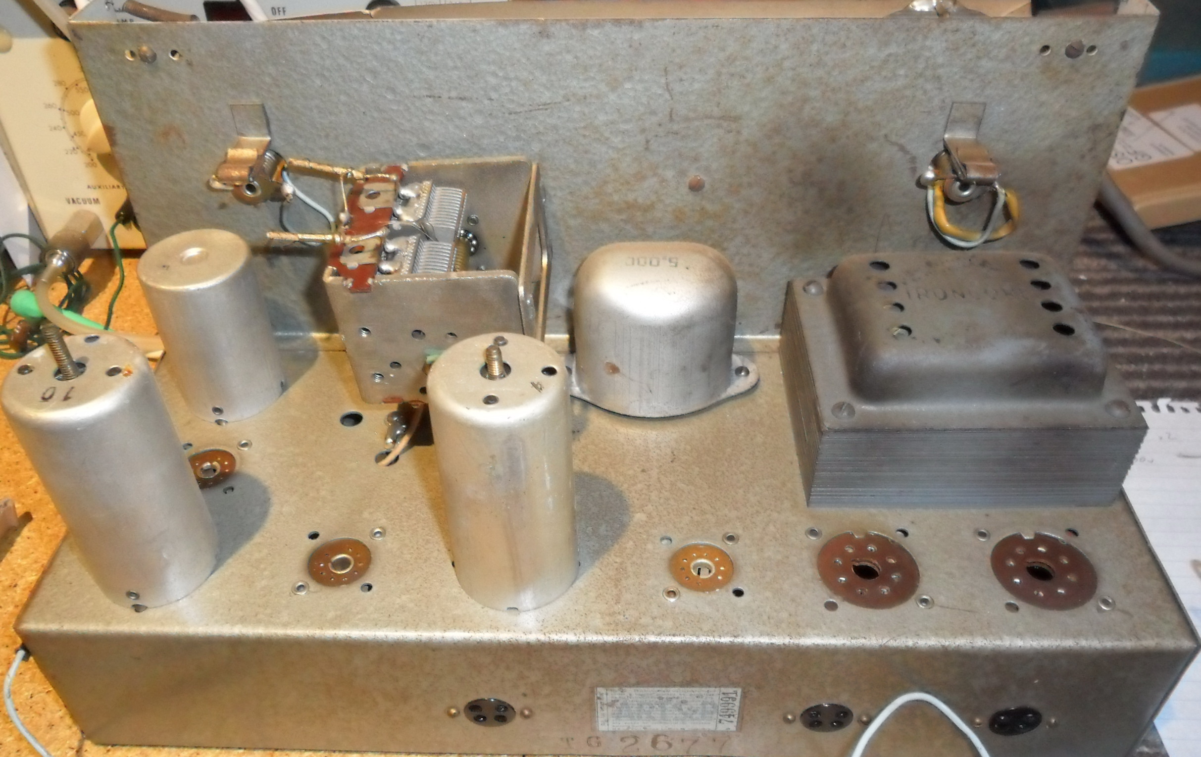

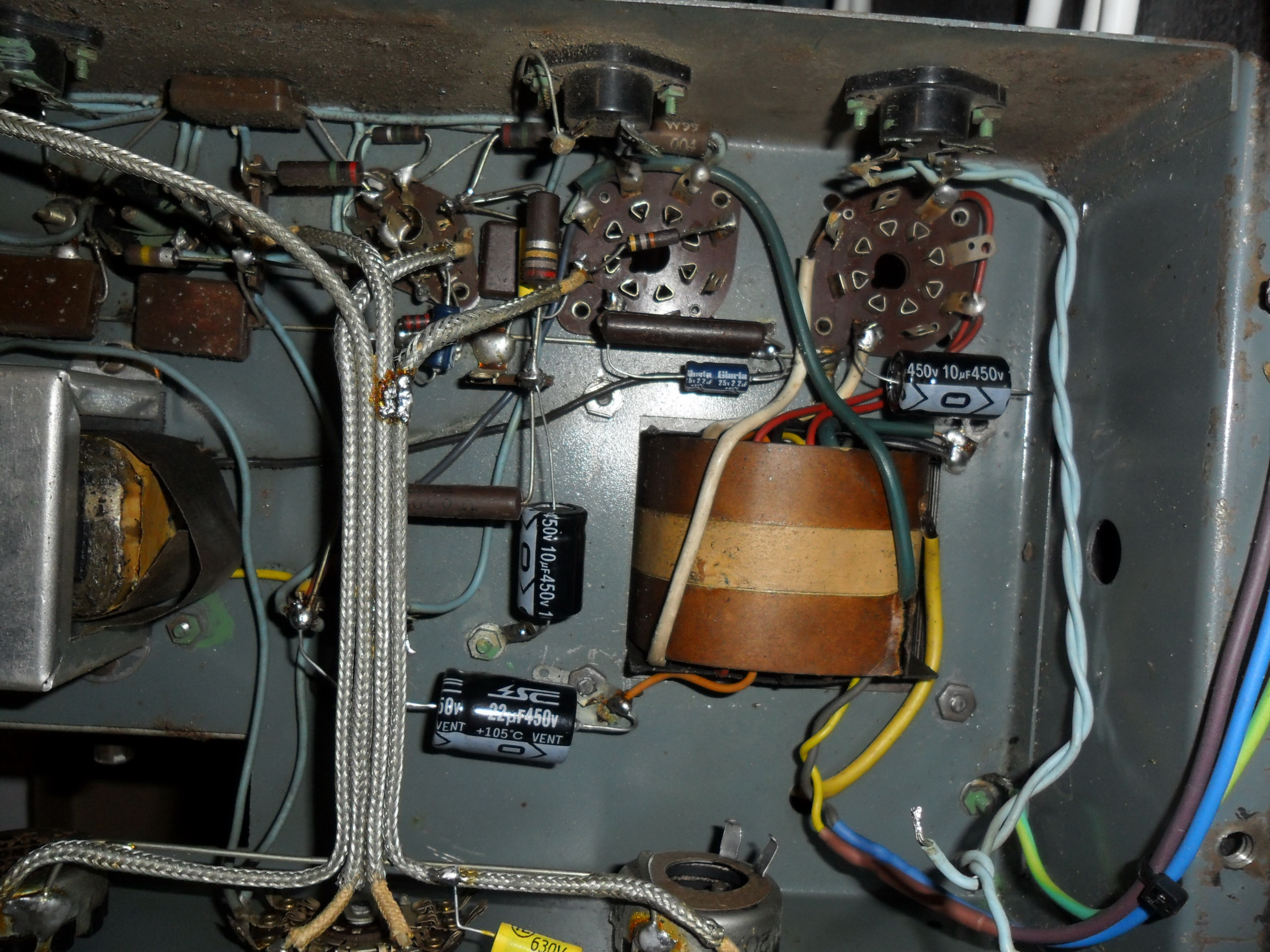
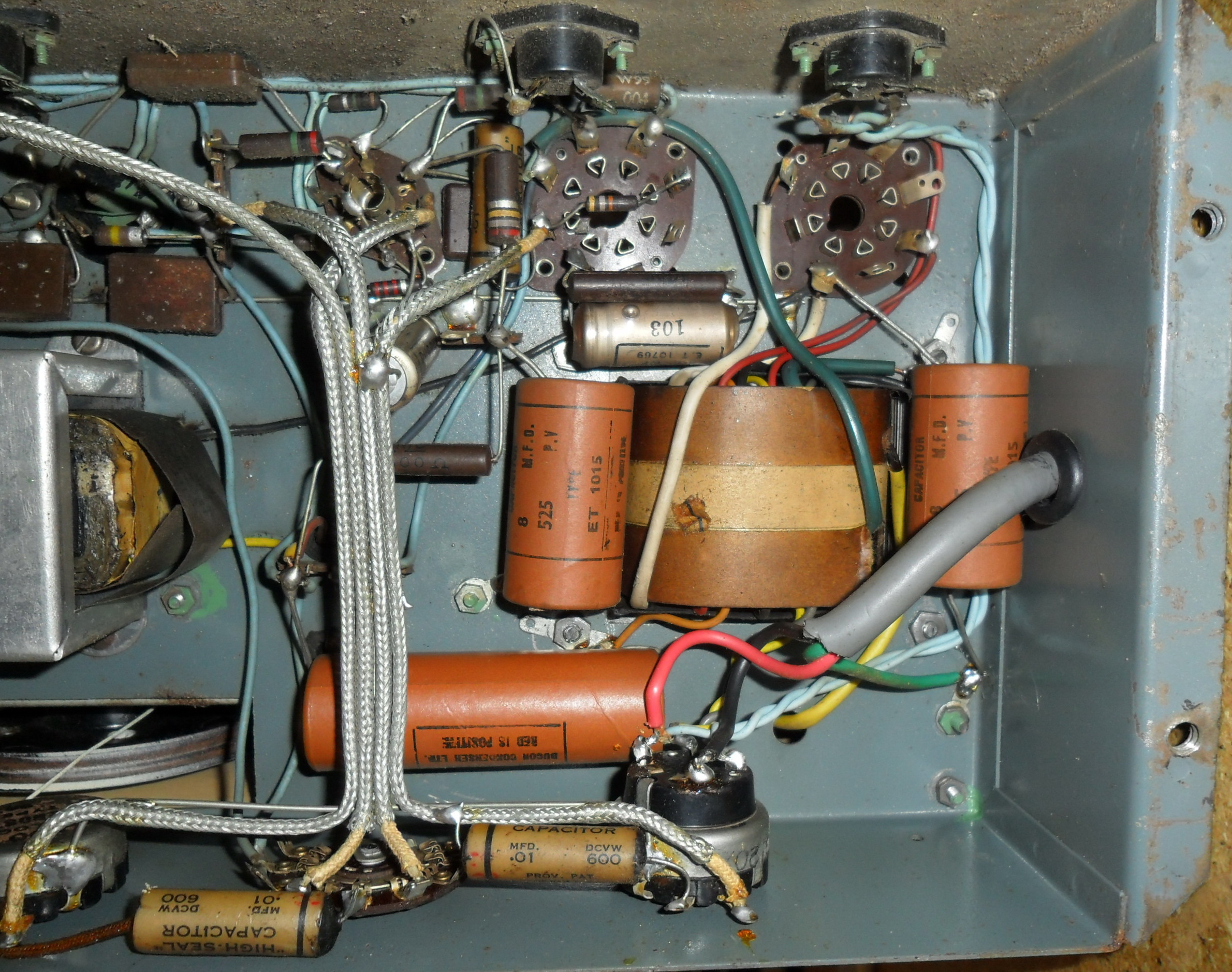
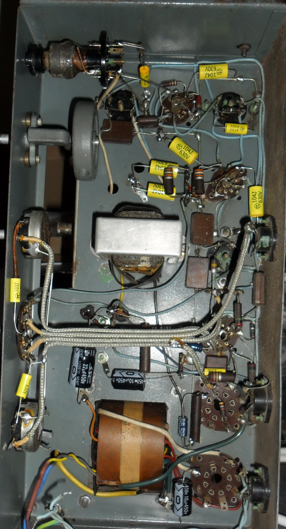
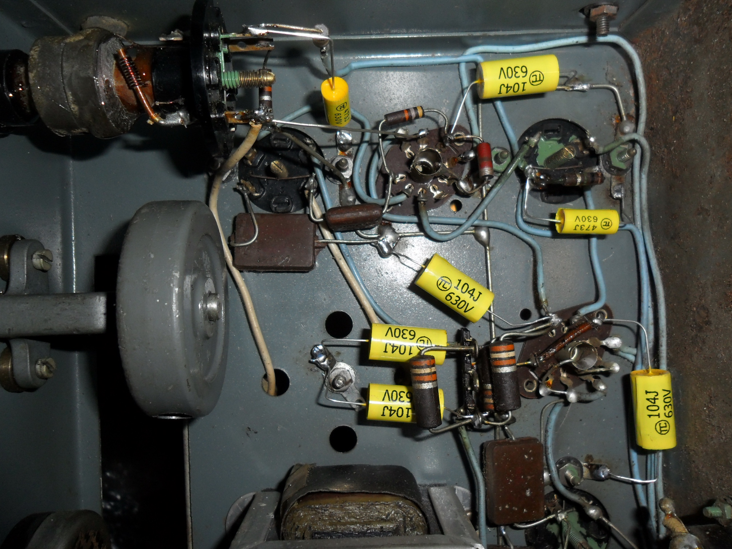
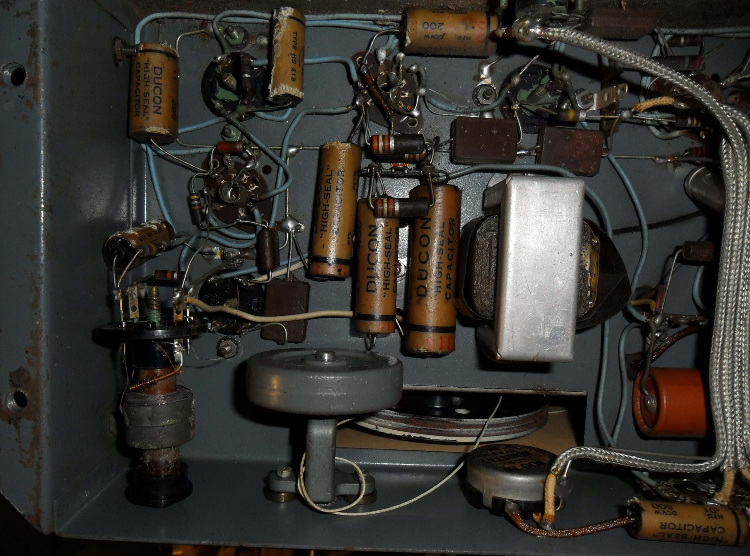


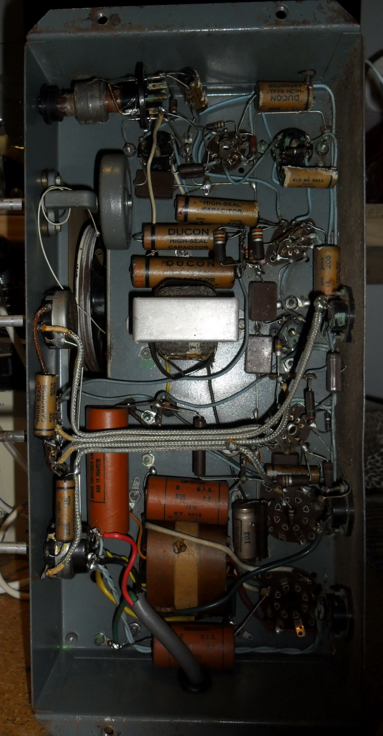
The brains removed from the cabinet, and the restore begins... All the valves were removed and cleaned up. They were all tested and passed as strong except the 6V6 output, so this was replaced and then put to one side whilst the chassis was cleaned and the dial face repainted white. Notice all the paper wax caps under the hood.. The power electrolytics all leaked, as did most of the paper caps. I don't believe in the snip and replace using the old leads routine. I like to carefully remove the old cap, dress the leads of the new one and solder it in exactly where the old one was. Moving components around can cause all sorts of grief and instability, so watch the placements. Replace the parts one at a time so to reduce the chances of screwing it up!
Mains safety tests FAILED with leakage to ground from active. Further tests proved the transformer to be OK (luckily) and the leakage was in the switch housing. Fastest way to fix that was to replace the switch-pot completely. The mains cord was also replaced and correctly anchored to the chassis. Copious quantities of heat shrink was also applied to live terminals, even though they are under-chassis.
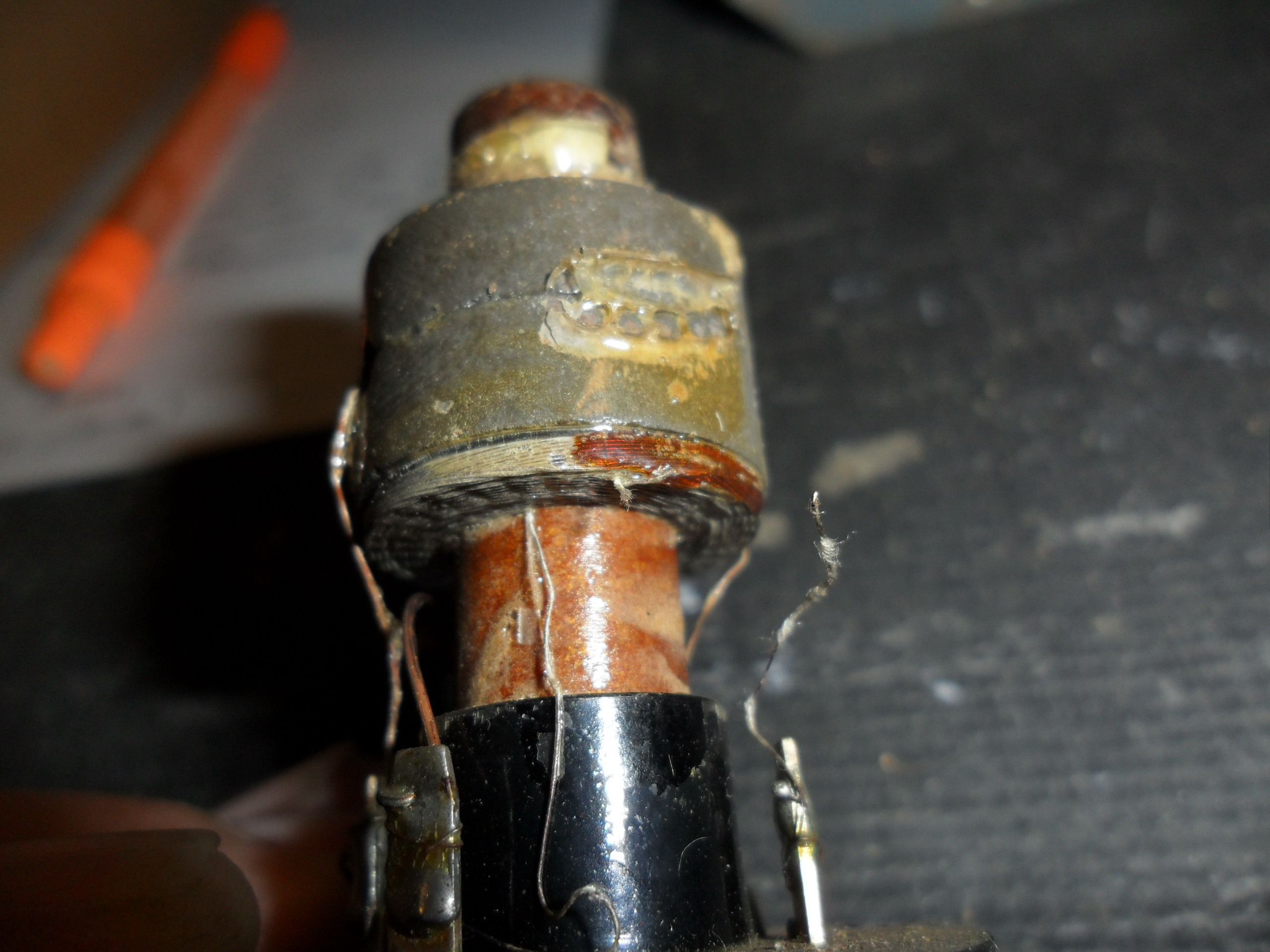
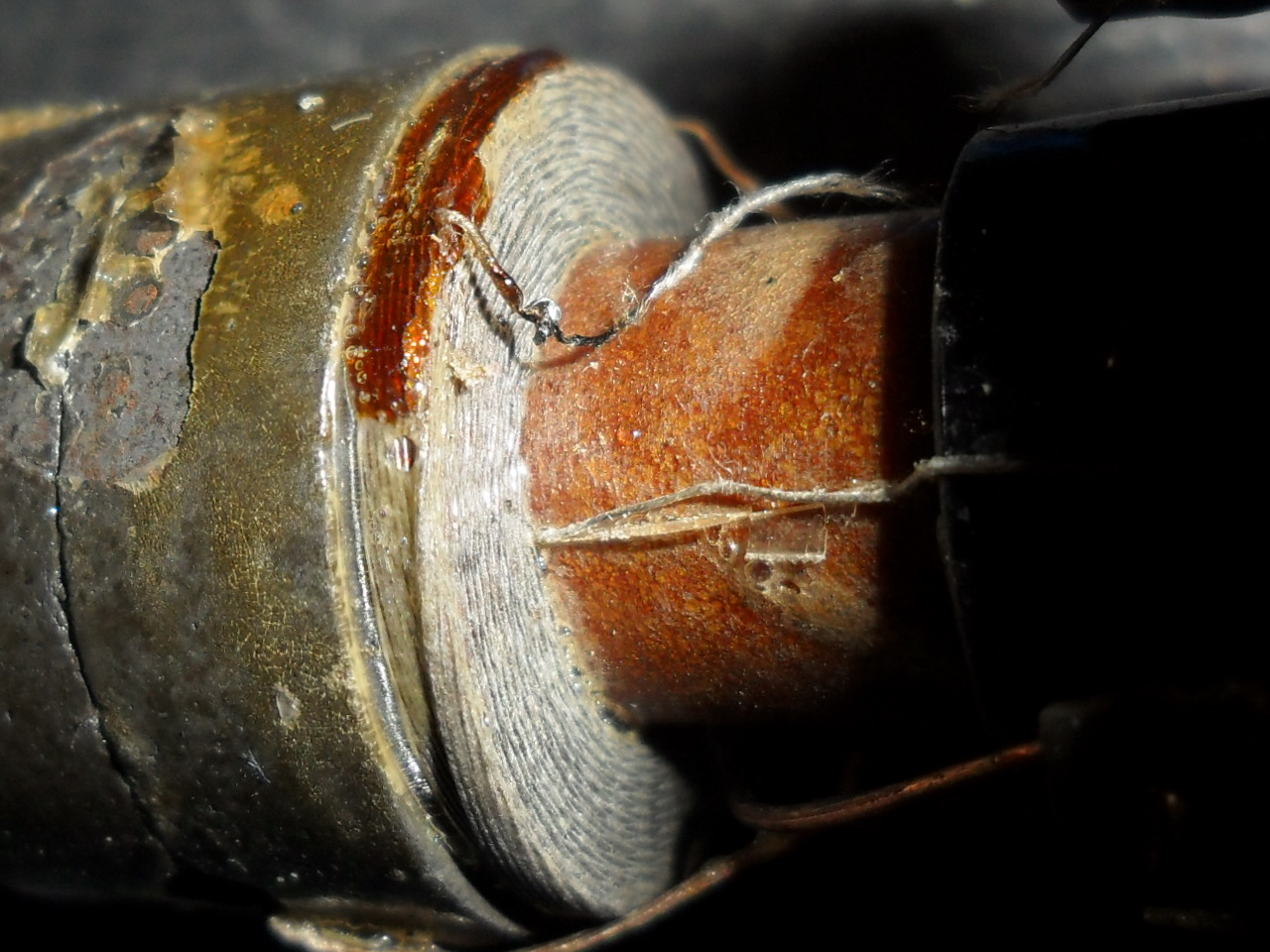
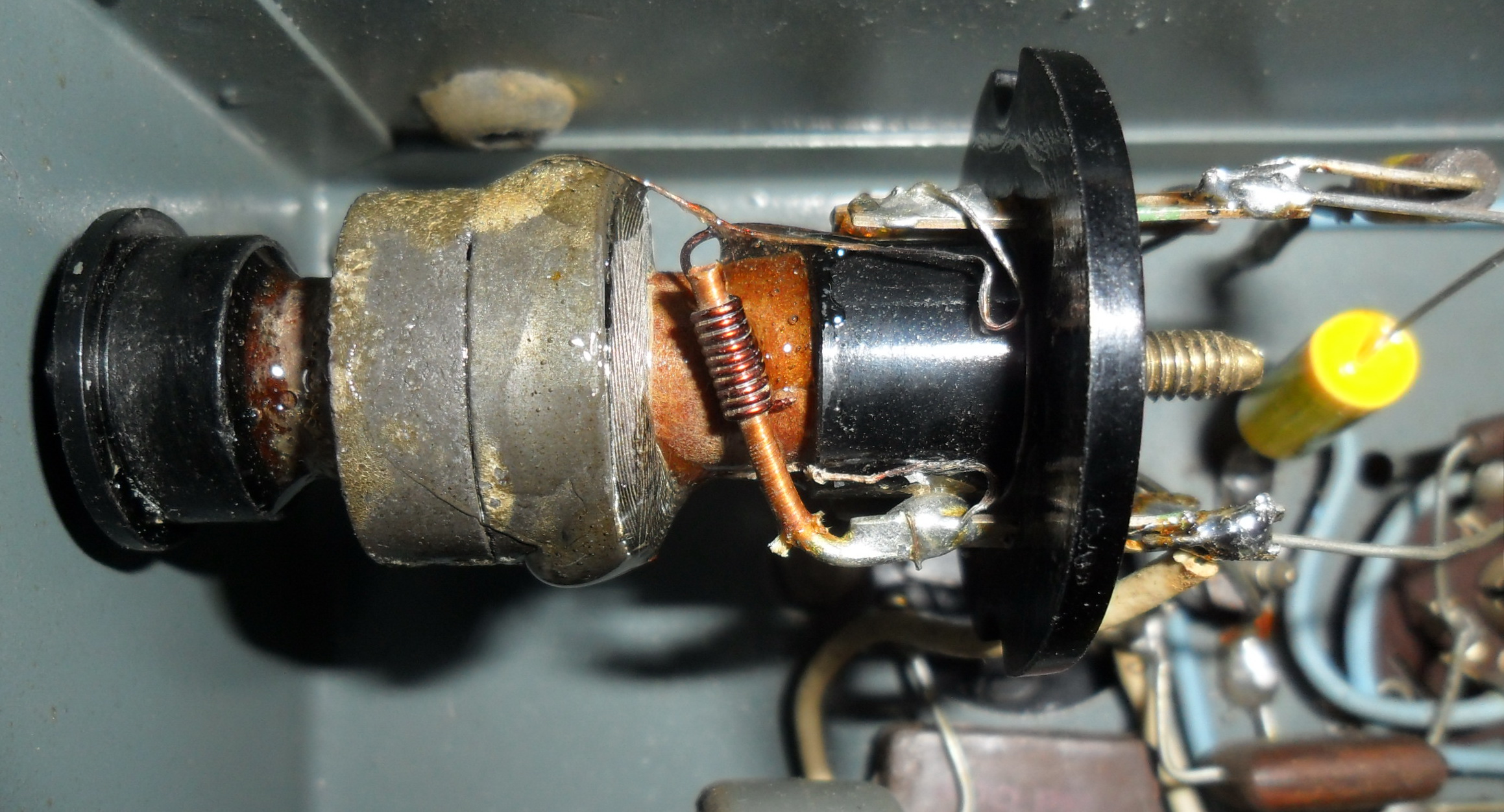
Running through the coil and transformer tests, the aerial coil was found to be open circuit and the former was no longer glued to the mountings, so it was floating loose in the chassis. Top-Left picture shows the former and all the unglued glue (!). Lower-Left picture shows where the open circuit was and luckily there was still a little bit of the wire sticking out of the coil. Top-Right picture shows the repaired coil and the final result is shown Bottom-Right. The former was epoxy glued back in the mountings with some additional epoxy run up to the coil to secure all the leads in their places. The coil is now back in place and working fine once again.
With everything cleaned up, and all the replacements made except for the volume switch-pot, time for some testing and alignment checks. The IF was pretty well on target and not much improvement was obtainable. The oscillator and aerial coils were touched up and the trimmers on top of the tuning gang were also touched up. These trimmers are old style and are adjusted by adding or removing turns of tinned wire effectively altering the capacitance. The outer wraps of wire should be on the ground side of the circuit as can be seen from the picture below. The outer wraps are connected to the frame of the tuning gang, so as wire is removed it can be pulled at right-angles prior to removal. This is handy in case you unwind too much, you can wind it back on, and at right angles it will not affect capacitance.
I did think about the look of the completed chassis with all those yellow caps there, but decided that it would be ok in this job. If you want it look original, all the old paper caps can be gutted by heating and pulling the guts out, then the new caps put back into the paper tubes and epoxied or re-waxed. Strangely enough, the dark brown colour of the wax is mostly dirt! When the wax is removed, the paper tubes are acually close to white, but you have to unroll one end of the tube to remove the guts.
Lastly, the dial cord was replaced, dial lamps replaced and a new light diffuser made. This was made from the backing sheets inside an old 19 inch LCD display panel. Carefully open up the panel and remove the glass, then remove the 1/4 inch thick plastic plate and below that you will find the diffuser sheets. I used 2 sheets, cut to size and held together with some open leatherwork rivets in the corners. The suspension springs were then hooked into the rivets.

Classic - Auto Radio/Gram
