

IRLP
Radio
Vintage


Live Status
VK2YLD
Steve...
Kurri Kurri,
New South Wales
Australia
email - vk2yld at dodo.com.au
REAL radios glow without smoke.


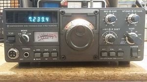
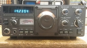
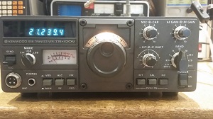
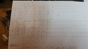
The whole thing revolves around the prefix digits that are displayed (the Mhz part) and then the VFO frequency is displayed as either 0-500Khz or 500-999Khz. The refix digits are loaded into IC13 on the counter board, a CD4019 CMOS data selector. The Mhz x10 digit into the 'B' registers and the Mhz digit into the 'A' registers. The BCD code is loaded backwards.. yes, backwards, lines ABCD loaded in elements 4321. This took some working from the schematic and the writing out a truth table for the incomming control lines from the bandswitch.
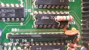
The published counter mod said to put a 15k resistor across pins 6 & 8 of IC13.. This pulls pin 6 low as pin 8 is ground. That results in the '28' changing to '20' and '29' going to '21'.. Good start..
Then it says to diode RB1 pin 2 to D8 cathode and also to RB1 pin 8 after the track to pin 8 is cut. Bridge the cut with another diode.. errr WRONG!
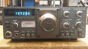
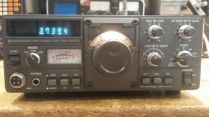
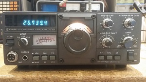
Turns out that the right way is to isolate RB1 pin 6 by cutting the track and bridge with a diode, then add diodes from RB1 pin 12 to pin 10 and pin 6. Then you get the display you are looking for 26.500 -> 27.999 in 3 steps. The original 28.000 now corresponds to 26.000 -> 26.500 and is inhibited giving a PLL Unlock as it is too far out for the VCO control voltage to handle. You could alter the oscillator frequency to bring it into range, but it is too far out of band to worry about.
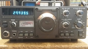
The last bit to be done was the conversion of the 10m band to 11m... Some more research located a how-to sheet on 11m conversion process at https://radioaficion.com/mods/ts-120s-mod-11m-conversion/, but this has been taken down recently for some reason, perhaps because ti was totally wrong!
The actual mod was to cut a wire on J15... Why cut it? Simply removing the pin from the plug and applying heatshrink would at least make it reversible. This fixed the radio bit, but the counter display is still wrong and the section of the mod that adjusted the counter was a total mess... Counter display went wrong on all bands, so I had to reverse engineer the original circuit and see where their mod came unglued.
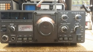
The TS-120v is the low power version of the 120s and has a 10w PEP output. It has SSB and CW only, so has limited modes. This unit presented with 20, 15 and 10m not functional. Only 2 dots in the display, which is an indication of PLL Lock failure.
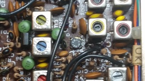
Some research on this problem via the 'net revealed that it was a common problem with a pair of transistors on the PLL board, Q24 and Q25 both 2SC460s. The story goes that they lose gain as they age. Both tested OK, but indeed the HFe had dropped to 20 and 18 respectively, when the datasheet said a minimum HFe of 30. The suggested replacement was 2SC945 according to the sheet at https://www.qsl.net/wb4kdi/Kenwood/TS-120S/TS-120_HELP.html point 5, PLL Unlock. However, as I found later, 2SC945s are and audio transistor and can't hack the 20Mhz signal here. Oh Poop!! This sheet only talks about unlock on 10 & 15m, so why was 20 unlocked too? Following the signals through the PLL board it was concluded that the FET Q23, 3SK40 was the culprit. Another obsolete device.
I seem to remember doing some repairs to the FT-101e and the front end and mixer both had 3SK40s in them and I replaced these successfully with BF981s. The same here, just open up the holes in the board to 0.8mm and the new FET fits easy. Now 20m locks OK, but the 15 & 10m are still crook. Looking back at the signals around Q24 and Q25 they are still low level. Pulled both 2SC945s out and retested them. Gain of 120 and 110, so a check of the datasheet then revealed that they are AF amps, not HF.. Poop! Repalced them again with a couple of 2N2222s as they are good to 300Mhz.. Now, after a retune of T1-5 cores, the PLL can be aligned to the specs in the manual and all working OK..
Repairing A Kenwood TS-120v

